A Low-cost Mechanically-Steered Phased-Array Polarimetric Doppler Weather RADar (WRAD)
Joint project between
Fraunhofer FHR and University of Bonn, Phase 1 & 2
Fraunhofer FHR: Stefano Turso (PI)
University of Bonn: Silke Trömel (PI) and Clemens Simmer (PI)
Abstract
Dense networks of inexpensive short-range weather radars have great potential to yield a fundamental advancement in the understanding of weather phenomena and achieve a timely reaction to extreme events. Due to the Earth curvature (see Fig. 1a) about 70% of the troposphere below 1 km cannot be observed by radar means (National Research Council et al., 1998). Consequently, traditional long-range weather radars (up to about 200 km range) are unable to provide coverage of the lower part of the atmosphere where most of the human interaction with weather phenomena takes place.
Composition of short-range weather maps (see Fig. 1b) appears therefore a viable solution to improve sensing of the lower troposphere, enhance spatial resolution and achieve a revisit time shorter than one minute.

Figure 1: (a) The Earth curvature effect. (b) Short-range weather maps composition.
Indeed, bi-axial mechanically steered weather radars usually require up to five minutes to complete a typical volume coverage pattern while many weather events evolve within tens of seconds and intense events change dynamics and structure within few minutes (Bluestein et al., 2003; Carbone et al., 1985).
Phased array radars (PARs) are based on Active Electronically Scanned Array (AESA) antenna apertures allowing for instantaneous beam steering. A PAR weather radar is optimally suited to improve temporal resolution and reach the goal of servicing up to one volumetric weather map per minute. Extensive research has shown that faster updates yield increased warning lead time, improve forecast accuracy and enhance probability of detection (Wilson et al., 2017).
With the goal of servicing weather maps with higher spatial and temporal resolution, the Fraunhofer Institute for High Frequency Physics and Radar Techniques (FHR) in partnership with the Institute for Geosciences, Department of Meteorology of the University of Bonn is developing a novel Phased-Array Radar (PAR) within the framework of PROM. The system will be deployed in range with the twin X-band Doppler radars at the JOYCE Core Facility and tested for assessment of data quality.
References
- National Research Council; Division on Earth and Life Studies; Commission on Geoscience, Environment and Resources; Board on Atmospheric Science and Climate, 1998: Atmospheric Sciences: Entering the Twenty-First Century,p. 181, National Academy Press, 2101 Constitution Avenue, NW Washington, DC 20418 USA, 364 pp., ISBN 0-309-06415-5.
- Bluestein, H. B., W.-C. Lee, M. Bell, C. C. Weiss, and A. L. Pazmany, 2003: Mobile Doppler radar observations of a tornado in a supercell near Bassett, Nebraska, on 5 June 1999. Part II: Tornado-vortex structure. Mon. Wea. Rev., 131, 2968–2984.
- Carbone, R. E., M. J. Carpenter, and C. D. Burghart, 1985: Doppler radar sampling limitations in convective storms. J. Atmos. Oceanic Technol., 2, 357–361.
- Wilson, K. A., P. L. Heinselman, C. M. Kuster, D. M. Kingfield, and Z. Kang, 2017: Forecaster performance and workload: Does radar update time matter? Wea. Forecasting, 32, 253–274, doi:10.1175/WAF-D-16-0157.1.
Status 2023
As a fundamental building block for assembly of the Active Front-End (AFE), a first version of the Active Row Module (ARM) has been prototyped following a modular plank approach. The ARM is engineered to function as a plug-in module, i.e. it requires provision of one single voltage source and features built-in commands translation towards the quad-core AESA chipset and related transceivers (Medium Power Front-Ends, MPFEs). It also includes all driving circuitry, voltage translation and interfaces to the associated subarray (see \(\text{Fig. 6a}\) and \(\text{6b}\)).


Due to the 5-bit phase and gain resolution, a fully automated test-setup is required for systematic validation. To this end, a custom software transmits a sequence of SCPI commands to a Vector Network Analyzer (VNA) and performs synchronized capturing of datasets. In this way one complete mapping of the available 4096 states can be capture per hour (see \(\text{Fig. 7a}\) and \(\text{7b}\)).


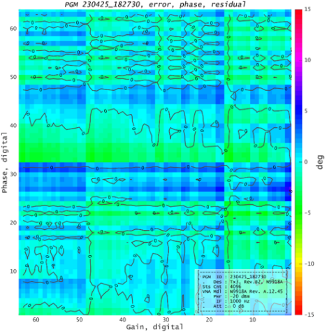
To exemplify, one phase-gain map (PGM) is shown (see \(\text{Fig. 8a}\) and \(\text{8b}\)). Deviations from nominal mapping is color coded to highlight measured state errors (left) and their correction (right).


A more quantitative representation is reported (\(\text{Fig. 9}\)) solely related to phase errors. By calibration, a definite improvement is noted, ranging around one order of magnitude.


Finally, beamforming is applied to the calibrated PGM to synthesize a \(30°\) steered beam with Taylor tapering (\(\text{Fig. 10}\)). Minimal deviations are observed against the theoretical pattern (blue curve, left). Beamforming on actual measurements (right) yields a pattern whose actual main features (steering angle, main lobe aperture and side lobe levels) are compatible with theoretical expectations.


Realization of additional ARMs will allow verification of the actual steering capability and beamforming performance of the full scale active front-end.
Status Summer 2021
Reflector-based weather antenna concept
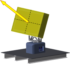
Sustainable deployment of a dense network of weather radars strictly requires low unitary and ownership costs. To this end, electronic scanning is limited to a single dimension (elevation) while a rotor provides mechanical steering in azimuth, as shown in Fig. 1.


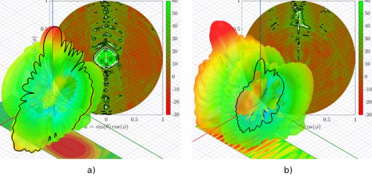
Indeed, while mechanical rotation can provide full azimuth coverage, at least electronic beam steering in elevation is necessary to achieve a timely volumetric sounding of the troposphere. This allows to overcome the major limitation of current operational polarimetric weather radars, which typically require up to five minutes to mechanically steer a large dish in two dimensions and provide complete sensing of the hemisphere. Technological breakthroughs like the availability of highly integrated MMICs promise to lower fabrication costs to a point of competition with mechanically steered weather radars. Distributed power generation removes the need of a costly power amplifier and rotary joint, reduces losses on transmit and grants graceful degradation. The entire back-end circuitry, including the first stage raw data processing and reduction, can rotate together with the antenna (as per the receiver over-elevation approach) to improve the receiver noise figure. Additionally, data reduction can be performed on-board before transmission of datasets across the slip-ring data lines (Turso et al., 2018). Allowing for non-inertial beam steering, phased array radars (PARs) are optimal candidates to improve temporal resolution and reach the goal of servicing up to one volumetric weather map per minute. However, large apertures are physically required to generate narrow beams, which for active antennas translates into higher complexity and cost compared to bi-axial mechanically steered solutions. To overcome this limitation, Fraunhofer FHR has envisioned a unique antenna concept (patent pending) to minimize complexity and cost with the ultimate goal of enabling mainstream use of AESA apertures within cost-sensible applications. Instead of directly using an AESA aperture to achieve both beam steering and gain generation, a simple parabolic cylinder is illuminated by an active feed for electronic steering in elevation while azimuthal focusing and beam symmetrization are obtained via the reflecting surface. This solution effectively decouples beam steering and gain generation, thus yielding minimization of complexity and cost (Turso et al., 2020). Upon reflection, beam symmetrization and gain enhancement are observed. Most importantly, near conservation of XPD feed performance are predicted at broadside, with acceptable degradation at 45° steering angle.

Figure 2: (a) Radiation pattern, surface current density and (u,v) XPD plots. Broadside illumination, simulations. (b) Radiation pattern, surface current density and (u,v) XPD plots. 45° beam steering, simulations.
Advanced AESA functions like dynamic tapering are available to further enhance beam and sidelobes symmetry at greater steering angles.
Outlook
Development of a suitable low-cost AESA front-end is a crucial step towards sustainable deployment of short-range netted weather radars able to generate composite maps with high space and time resolution, and reach the final goal of improved monitoring of the lower troposphere.
Initial results from the weather radar initiative at Fraunhofer FHR in the framework of PROM are profiled, showing a potential for novel concepts and designs to meet strict polarimetric requirements and generate valid weather radar observations within cost-constrains.
References
- Turso, S., T. Bertuch, S. Stanko, P. Knott, S. Trömel, and C. Simmer, 2018: A Low-Cost Mechanically-Steered Weather Radar Concept, Radar Conference (RadarConf), 2018 IEEE.
- Turso, S., C. G. Salzburg, M. Vizcarro, and T. Bertuch, 2020: A Novel Antenna Concept for Weather Applications Based on a Cylindrical Parabolic Reflector, 2020 IEEE Radar Conference (RadarConf20), Florence, Italy, pp. 1-4, doi: 10.1109/RadarConf2043947.2020.9266385.
Status 2020
Tile sub-array with enhanced cross-polarization discrimination
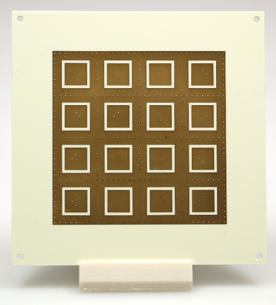
A new generation of RF chipsets featuring high level of functional integration allows for reduction of cost, complexity and development risk at X-band. However, matching the same data quality of bi-axial mechanical solutions is essentially independent from the technological implementation and strictly requires unbiased estimation of polarimetric moments to yield consistent classification of hydrometeors over the entire scanning volume (Zrnic et al., 2011). Consequently, one of the most stringent requirements specific to weather sensing is the achievement of a cross-polarization discrimination (XPD) in excess of 30 dB (Zhang et al., 2011). Investigation on methods to improve the polarization purity have been conducted to ensure feasibility within cost constraints. Specifically, an optimized design of a tile sub-array based on specular antenna excitations has been pursued and finely tuned to reach the required polarization performance (Vizcarro et al., 2019). Such scalable tile (see Fig. 1) can be further assembled to function as the sub-array of an electronically-steerable aperture.


Instrumental validation essentially supports theoretical expectations concerning polarimetric performance, also for beam directions off-broadside. Three-dimensional radiation patterns and XPD plots in (u,v) coordinates (see Fig. 2) show good agreement in between simulations and measurements. In particular, XPD levels better than 40 dB are reached at broadside. At 45° steering angle about 30 dB XPD are still observed.

Figure 2: (a) Tile sub-array radiation diagram and (u,v) XPD plots, simulations. (b) Tile sub-array radiation diagram and (u,v) XPD plots, measurements.
References
- Zrnic, D. S., R. J. Doviak, 2011: System Requirements for Phased Array Weather Radar, https://www.nssl.noaa.gov/publications/par_reports/LMCO_Consult2.pdf
- Zhang, G., R. J. Doviak, D. S. Zrnić, R. Palmer, L. Lei, and Y. Al-Rashid, 2011: Polarimetric Phased-Array Radar for Weather Measurement: A Planar or Cylindrical Configuration?, J. Atmos. Oceanic Technol., 28, pp. 63–73, 2011, doi: 10.1175/2010JTECHA1470.1.
- Vizcarro, M., S. Turso, C. G. Salzburg, and T. Bertuch, 2019: A Dual-polarized X-band Patch Antenna Sub-array with Low Cross-polarization for Weather Radar Applications, 20th International Radar Symposium (IRS), Ulm, Germany, Jun. 2019, pp. 1–6, doi: 10.23919/IRS.2019.8768175.